How do you make calculations for the inverter you made to know it's 500W. I am working on an irf740 mosfet based inverter. Can you please drop your number let's talk about this better maclee My email: Nzubeeleke@gmail.com maclee:
WELCOME TO THE HOME OF SHARING IDEAS, SHARING TALENTS AND NOT SHARING ABUSES AND INSULTS
Please this post is not for people who wants to learn how to solder, and for people that cannot identify the simplest components.
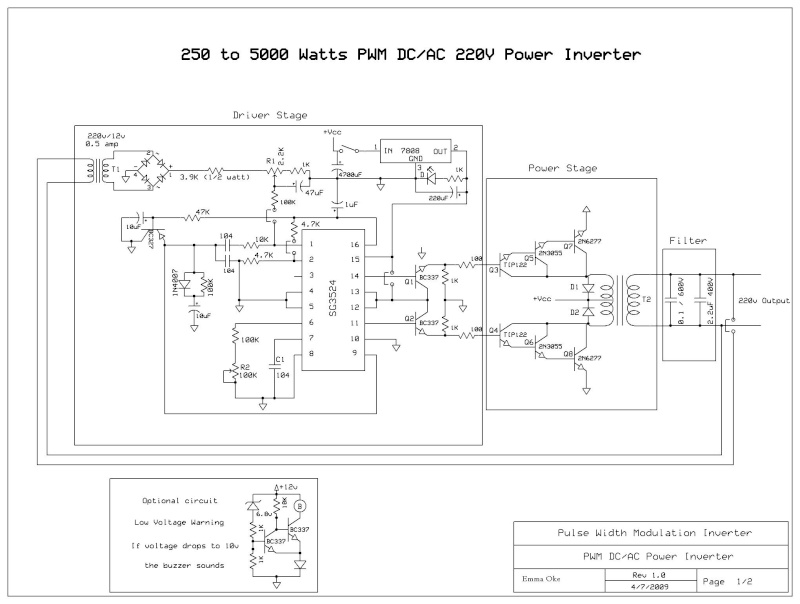
So as the founder of the post I would like to start up with a simple 250 to 5000 watts PWM DC – AC 220v power inverter. I hope this forum allows the display of .jpg and .pdf file -The schematic circuit design is for a 250 watt output, while the pics are of my 1500 watts inverter that i built, to increase the power of the circuit you have to add more of the Q7 and Q8 transistors in parallel, each pair you add will increase your power by 250 watts, ex: to get 750 watts of power from the inverter you need to add 2 of Q7 and 2 of Q8 to the original design.
--If you increase the power transistors you have to enlarge the T2 transformer to match the new needs, the circuit's transformer is rated 25 amps to handle 250 watts of 220v, for every 1 additional amp you need on the 220v side you have to increase 10 amps on the 12v side, of course there are limits to the thickness of the winding so if you need more than 750 watts i recommend that you use a 24VDC supply instead of 12 volts:
DC voltage and Transformer "T2" winding recommendation:
Power Supply Winding
750w 12VDC P:24V "12-0-12" / S:220V
1500w 24VDC P:48V "24-0-24" / S:220V
2250w 36VDC P:72V "36-0-36" / S:220V
3000w 48VDC P:96V "48-0-48" / S:220V
3750w 60VDC P:120V "60-0-60" / S:220V
4500w 72VDC P:144V "72-0-72" / S:220V
5250w 84VDC P:168V "84-0-84" / S:220V
*The transformer should be "center tapped" at the primary side.
**You can make the secondary 110v if needed.
***The transformer in the pic is a custom made (48V center tapped / 220v ) 2000 watts
--R1 is to set the PWM to 220v
--R2 is to set the frequency to 50 or 60 Hz
--Use either tantalum or polyester film "as in pic" for the 104 caps, ceramic disc caps change value once hot and this in turn changes the frequency of the inverter so they are not recommended.
--Wiring should be thick enough to handle the huge amps drain from the batteries.
--The design does not include a battery charger since each person will be building a custom version of the inverter with specific power needs.
--A cooling fan will be needed to reduce heat off the heat sinks and transformer, i recommend getting a 220v fan and connecting it to the output T2 transformer, when you power up the circuit the fan will start this will always give you a simple way to know that 220v is present and everything is OK..
--2 circuit breakers are recommended instead of fuses, one on the DC side and one on the AC side, depending on your design
Ex: for a 24vDC ( 1500 watts design ) put a 60Amp breaker on the DC side and a 6Amp on the AC side.
For every 1amp of 220vAC you will be draining like 8 to 10 Amps from the 12v battery, make your calculations !
-- The 2 Heat sinks should be big enough to cool the transistors, they are separate and should NOT touch each other.
--Be cautious when building this circuit it involves high voltage which is lethal, any part you touch when the circuit is ON could give you a nasty painful jolt, specially the heat-sinks, never touch them when the circuit is on to see if the transistors are hot !!
http://i76.servimg.com/u/f76/18/48/99/32/250_to12.jpg |


