For Interested Engrs: Learn Autocad On This Thread - Career - Nairaland
Nairaland Forum / Nairaland / General / Career / For Interested Engrs: Learn Autocad On This Thread (5612 Views)
Learn AUTOCAD & PDMS and AUTODESK INVENTOR In Ibadan or LAGOS. / Civil Engrs In D House / Geologists And Mining Engrs: Let's Talk Here (2) (3) (4)
| For Interested Engrs: Learn Autocad On This Thread by hal9000: 12:10pm On Jul 25, 2013 |
I was initially inspired by esere's Excel for Beginners thread, and after thinking long and hard about it, I’ve decided to share my knowledge online, free of charge, with anyone who is interested and dedicated enough to learn. Every student likes to be sure that his/her teacher is qualified to teach the subject, so a brief bio is called for. I am a self-taught freelance AutoCAD technician, and I’ve used the software professionally for going on 5 years now. I read somewhere that doing volunteer projects are a great way to broadcast one’s skills to potential employers/clients and enhance one’s career, so this is me doing some volunteer work.  Ok, let’s get to it. Now, AutoCAD is VERY long and VERY wide; there are so many tools, so many menus, and several ways of doing so many things. I cannot promise that I will cover everything; But I can promise that I will TRY. I will try to cover as much as I can, as gently and with as much explanation as I can. If you are willing to put in interest, hardwork, practice, and a good amount of brain-power and imagination, then I promise that within 3 weeks, this thread will turn you into a pretty good AutoCAD draftsman. You will learn the same way I learnt: by reading online tutorials AND lots of practice. |
| Re: For Interested Engrs: Learn Autocad On This Thread by hal9000: 12:14pm On Jul 25, 2013 |
Ok, first things first. What do you need to learn AutoCAD? 3 things: 1. A good laptop/PC. We’re starting with basics, so you don’t need anything superfast yet. A system with 1gig of RAM should do. 2. The AutoCAD software installed in your system. I’ll be using AutoCAD 2007 cos it’s the more popular version in Nigeria, but once in a while I’ll also bring in new tools from AutoCAD 2010. You can contact your local software vendor/stores for original AutoCAD and other Autodesk products. If you are a student, you can download and install a trial version of the latest AutoCAD straight from the Autodesk website. If you have installation issues, or you are anywhere near Port Harcourt, then PM me and we’ll see about fixing you up. Abeg, Seun totally prohibits promotion of “oluwole” things, so please my hand no dey am oo!!  3. Lastly, you need to be sure that you WANT to learn this program. You can easily go to some training school and pay between 15k – 30k, then sit through 7 boring classes, after which they tell you that’s all. Or, you can pay attention, force your brain to concentrate on the words on your screen, force yourself to follow my instructions line by line and try to replicate the simple steps, tools, and skills I will teach you at no charge. Let me say it categorically: the people I have in mind when I started this thread are the numerous engineering graduates and students who can’t afford the many expensive CAD training centers that litter Lagos and Port Harcourt. I could have posted links to training videos online and on youtube, but I know that many young Nigerians don’t have access to wifi and can’t afford the bandwith required to watch these videos. So I am going to do it the old fashioned way: write “lecture notes” and post explanatory pictures; hopefully that will suffice. I’ll start tomorrow morning with the first post. If interested, kindly indicate with a comment. Ciao! 8 Likes |
| Re: For Interested Engrs: Learn Autocad On This Thread by Nobody: 1:41pm On Jul 25, 2013 |
I am soooo in, being an undergraduate building student and with this strike issues i could really use this. fire on!! |
| Re: For Interested Engrs: Learn Autocad On This Thread by ayogabriel(m): 2:54pm On Jul 25, 2013 |
So interested, thanx |
| Re: For Interested Engrs: Learn Autocad On This Thread by ajayioluwatobi(m): 6:06pm On Jul 25, 2013 |
BimiOne: I am soooo in, being an undergraduate building student and with this strike issues i could really use this. fire on!!building student too, which skull and level |
| Re: For Interested Engrs: Learn Autocad On This Thread by Nobody: 6:54pm On Jul 25, 2013 |
ajayioluwatobi: building student too, which skull and level100level, ATBU, you? |
| Re: For Interested Engrs: Learn Autocad On This Thread by Sirniyeh(m): 6:54pm On Jul 25, 2013 |
Interested! |
| Re: For Interested Engrs: Learn Autocad On This Thread by duality(m): 8:14pm On Jul 25, 2013 |
Bros I am very interested. please make your explanations short and simple so that every one can follow. even if it takes a hundred years, it will be very effective. God bless. |
| Re: For Interested Engrs: Learn Autocad On This Thread by ajayioluwatobi(m): 8:31pm On Jul 25, 2013 |
BimiOne: 100level, ATBU, you?unilag, 300l. building const. Is broad course, u learn civil work, building design n const. boq, estimation, piping work, steel design n const, maintenance n reliabitation, concrete design n const, specification, electricity, etc . I love it. |
| Re: For Interested Engrs: Learn Autocad On This Thread by Nobody: 9:25pm On Jul 25, 2013 |
ajayioluwatobi: unilag, 300l. building const. Is broad course, u learn civil work, building design n const. boq, estimation, piping work, steel design n const, maintenance n reliabitation, concrete design n const, specification, electricity, etc . I love it.wow! i'm loving it too.But Lets not derail the gentleman's thread and continue in the builder's thread. |
| Re: For Interested Engrs: Learn Autocad On This Thread by double3(m): 9:39pm On Jul 25, 2013 |
This is exactly the kind of stuffs we need on nairaland,I'll also appreciate it if other autocad gurus can share certain tips to complement this young mans efforts..good work man,I'm so in n would assist in my own lil way too.. |
| Re: For Interested Engrs: Learn Autocad On This Thread by hal9000: 6:29am On Jul 26, 2013 |
ayogabriel: So interested, thanx BimiOne: I am soooo in, being an undergraduate building student and with this strike issues i could really use this. fire on!! Sirniyeh: Interested! duality: Bros I am very interested. please make your explanations short and simple so that every one can follow. even if it takes a hundred years, it will be very effective. God bless. double3: This is exactly the kind of stuffs we need on nairaland,I'll also appreciate it if other autocad gurus can share certain tips to complement this young mans efforts..good work man,I'm so in n would assist in my own lil way too.. Thanks for showing interest, everyone. Like any good teacher, i really appreciate it when my students show enthusiasm... (see me forming Oga Headmaster,  ) Anyway, I promise i'll try my best. ) Anyway, I promise i'll try my best. |
| Re: For Interested Engrs: Learn Autocad On This Thread by hal9000: 6:43am On Jul 26, 2013 |
Alright, class is in session...  Lesson One: Introduction to AutoCAD 2007 AutoCAD is a software application for computer aided designs (CAD) and drafting. Drafting means any technical drawing that requires precise representation of distances and angles. AutoCAD is owned by Autodesk Inc. and the latest version is AutoCAD 2014, released March this year. Alright, enough grammar. If you haven’t opened your Autocad software yet, then do so. Double click on the icon on your desktop, or start from your windows start menu, navigate to programs, and find ‘AutoCAD 2007’ under “Autodesk” folder. 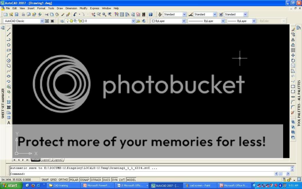 The above pic is what your screen should look like. It is called “AutoCAD 2007 2D wireframe environment”. If your autocad screen isn’t showing something similar, then just take a screenshot and post it with your comment here; I’ll tell you how to get it in shape. You take a screenshot by pressing the “PrtSc” button on your keyboard, then click on your system’s windows ‘Start’ button > All programs > Accessories >’Paint’. When Paint program opens, press “Ctrl+V” and your screenshot will paste there. You can now save it as a pic. By the way, if you don’t have AutoCAD in your system (and you are as clueless as one goodluck guy as per how to have it installed in your system), then PM me and we’ll see about getting you fixed up. AND if you don’t have a system at all, then sorry mate, your case na im worse pass. Ok, ok, just try make friends with someone that has a PC/laptop, then convince him/her that learning AutoCAD will be good for both of you. You should know what to do after that. 1 Like |
| Re: For Interested Engrs: Learn Autocad On This Thread by hal9000: 6:53am On Jul 26, 2013 |
Back to the lesson. I’ll describe a few things first: look at the next pic below. 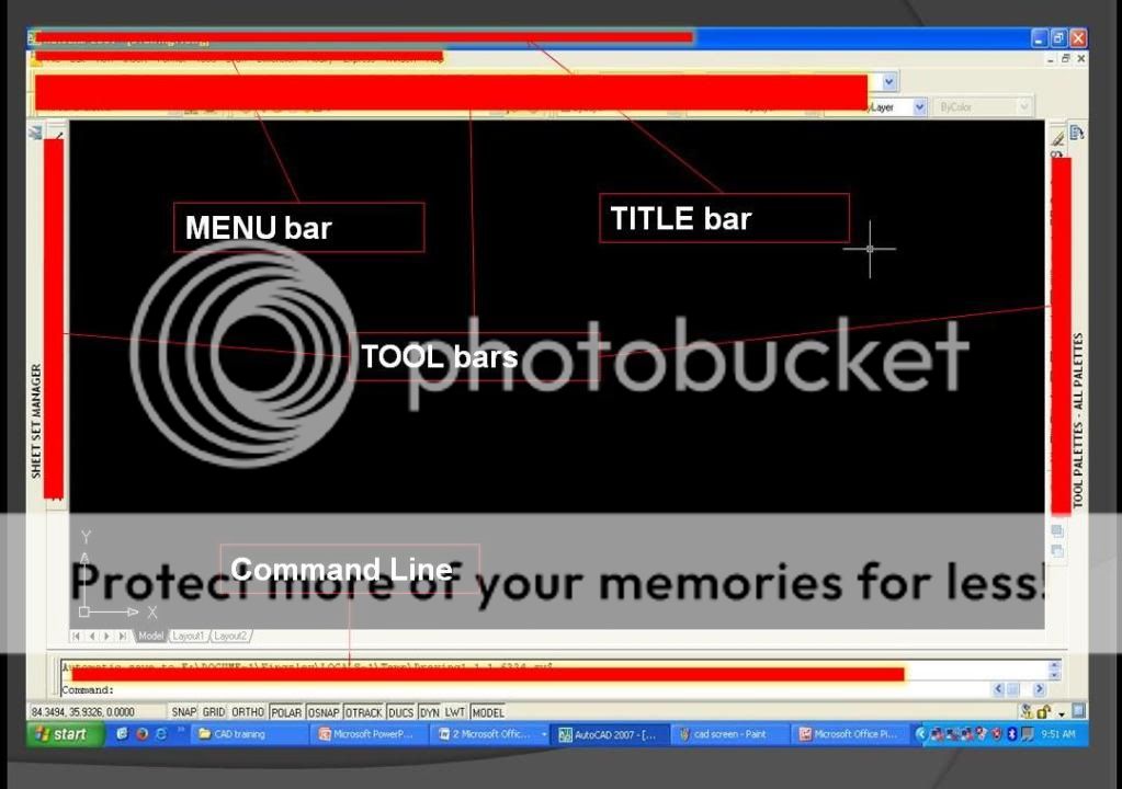 See the places I marked with red paint and indicated as “Title bar”, “main menu bar”, and “toolbars”. Compare those places with your own autocad screen. The toolbar on the left side on the screen is called the ‘Draw toolbar’, while the one on the right is the ‘Modify toolbar’. If you click on ‘Draw’ on the main menu bar and compare with the Draw toolbar (that’s the toolbar on the leftside), you’ll how their icons are very similar. Hover your cursor over some of the icons; can you see their names showing? You should see “line”, “polyline”, “polygon”, “rectangle”, “circle”, etc. Now leave that toolbar for a moment (if you’ve mistakenly clicked on anything, just press “Esc” button twice and you’ll be back to normal). Click on ‘Modify’ on the main menu (same way you did with ‘Draw’) and compare with the Modify toolbar on the right. Oya, hover your cursor over some of the icons; can you see “erase”, “copy”, “mirror”, “offset”, etc. I’ll teach you how to use all that soon enough. Next thing I want you to take note of is the “Command line” (refer to pic above if you don’t know where it is). Now pay attention. There are at least 3 ways to draw anything in AutoCAD. For example, let’s say you want to draw a line: (a) You can click on the “Line” icon from the draw toolbar on the left. Go ahead and click the line icon; now look at the Command line, see what it is reading? Specify first point: [/i]Just click anywhere you like as first point, and look at the command line again. [i]Specify next point or [undo]. Click on somewhere a little distance from your first point. Still reading “specify next point or [undo]” right? Now press ‘enter’. Can you see the line you have just drawn? Yeah, you can smile a little now. (b) Second way you can draw a line, go to main menu bar, click “Draw”, and select “Line”. Draw another line same way you drew the first. You see they’re both drawn the same way, right? (c) Third and easiest way, just click on the command line (along that line where you see Command:), yes, click there and just type “L”, and press ‘enter’. Voila, you’re in line drawing mode again! That ‘L’ you just pressed is called a “Command Keystroke”. Almost every drawing or modifying tool in AutoCAD has a command keystroke and it can be used instead of going around looking for the icon you need. The best thing about keystrokes is that they are the same is ALL versions of AutoCAD i.e. whenever you press ‘L’ on the command line in any version of AutoCAD and press enter, you’re ready to draw a line. Last thing for now, I’ve attached a jpeg table of a few tools you’ll be using very frequently. The first column describes the tool; the second column shows what its icon looks like (on the draw or modify toolbar); the third shows its keystroke; and the last column tells you how to locate it from the main menu. 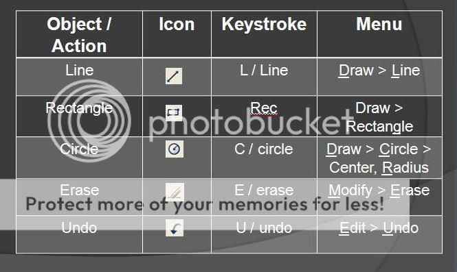 Please kindly note those keystrokes, cos I’ll be mostly using them in teaching. Of course you can use the icons instead, but a good advantage of keystrokes is that even when you can’t find the icon or maybe you’re using a different a version of AutoCAD, you can just type your keystroke and you’re good to go. Okaaaay, that’s the end of this morning’s class. Next lesson I’ll be teaching “Accurate Input”, and we’ll be drawing some basic shapes. Hope to post that this afternoon (or in the evening, at most). In the meantime, you can practice drawing a few lines, rectangles and circles; see if you can figure out how they work (tip: watch your command line for instructions!). If you have questions, PM me or just comment with it right here. I’ll do my best to explain. God bless! |
| Re: For Interested Engrs: Learn Autocad On This Thread by double3(m): 11:09am On Jul 26, 2013 |
Good work man....please I have a question,though its on 3d modeling:...assuming I wanto draw on the curved surface of a cylinder in autocad(2010) how do I go about it, I have tried adjusting the ucs to the curved surface of the cylinder yet it wouldn't work, I have also tried using dynamic ucs n yet no success,what I'm I doing wrong??( Sorry for jumping into another lesson) . |
| Re: For Interested Engrs: Learn Autocad On This Thread by hal9000: 11:59am On Jul 26, 2013 |
^^^@double3, I'm guessing u want to modify the cylinder with an extruded shape of what u want 2draw on its surface. Just send your questions to me thru cadtechy@gmail.com; that way we don't derail and scare away the young learners. ------- Still working on next lesson's post... 1 Like |
| Re: For Interested Engrs: Learn Autocad On This Thread by hal9000: 5:23pm On Jul 26, 2013 |
Lesson Two: Accurate Input In the lesson we’re going to be drawing some basic shapes using the following drawing and modifying tools: Line (L), Rectangle (REC), Zoom (Z), Undo (u), Copy (CO), and Move (M). See if you can identify them on their respective toolbars. Before we start off, I want to refresh your memory of X,Y-coordinates. Think of drawing in autocad as the same as drawing on a graph paper; every point has an x- and y-coordinate. There’s the z-coordinate, too, but we’re still doing 2D so we can leave that for now. Look at the pic below. 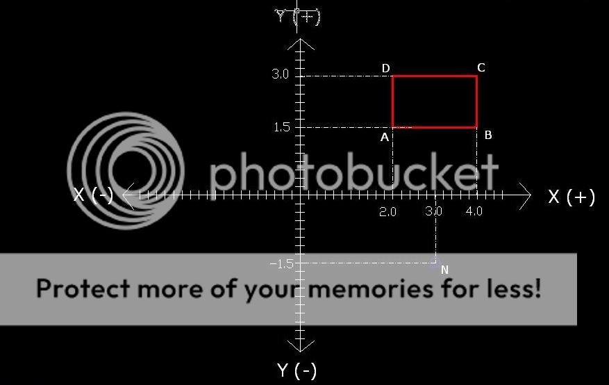 The rectangle has vertices ABCD. From the pic, we can see that the coordinate of A is (2.0, 1.5), B is (4.0, 1.5), C (4.0, 3.0), and D (2.0, 3.0). And the coordinate of point N is (3.0, -1.5). Thus you can see that coordinates are always given in terms of (x,y), the x-coordinate always before the y-coordinate. Time try to draw something yourself. First of all open a new autocad drawing template by going to main menu File > New. A dialog box will show up; select “acad” as in the pic below (this is the default drawing template), and click “Open”. Now you’re set. 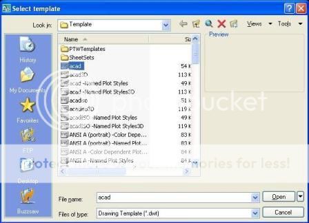 You’re going to draw a rectangle now. Start the rectangle command by typing ‘rec’ and press ‘enter’ (or just click the Rectangle Line icon). Watch the command line… Command: rec RECTANG Specify first corner point or [Chamfer/Elevation/Fillet/Thickness/Width]: Type 0,0 and ‘enter’ Specify other corner point or [Area/Dimensions/Rotation]: Type 20,15 and ‘enter’ Don't worry if you don't see what you drew. Just press ‘z’, ‘enter’, and then ‘e’ and ‘enter’ again. Can you see the rectangle now? Congratulations! By the way, that ‘z’ you typed is the keystroke for the “Zoom” tool (see if you can find the zoom tool in the toolbar under the main menu). In autocad, when you press a keystroke or click an icon, a list of options will show up in your command line. Press that ‘z’ and ‘enter’ again; now look at the command line: Command: z ZOOM Specify corner of window, enter a scale factor (nX or nXP), or [All/Center/Dynamic/Extents/Previous/Scale/Window/Object] <real time>: Those options within the [] bracket are the ones you can choose from, and you choose by typing the first letter of each option. So typing ‘e’ and ‘enter’ chooses the “Extents” option. Alright, we’ll come back to Zoom later. Let’s move on. Absolute, Relative and Polar Coordinates A coordinate is absolute when it is given with the exact x- and y- values. An example is the rectangle you just drew, I gave the coordinates as (0,0) and (20,15). On the other hand, a relative coordinate is one that is given relative to a previously known point. Relative coordinates are always preceded by the symbol ‘@’. Look at the pic below. The outer rectangle is same as the one you just drew (i.e. 20units length, 15units width). Now lets draw the shapes inside it.  Start with rectangle on the lower left. As you can see its coordinates are all absolute (x,y). Use the line command to draw it. Your command line should read thus: Command: [/i]Type ‘L’ and enter [i]LINE Specify first point: Type 2,2 and enter Specify next point or [Undo]: 4,2 and enter Specify next point or [Undo]: 4,4 and enter Specify next point or [Close/Undo]: 2,4 and enter Specify next point or [Close/Undo]: Just type 'c' and enter (Remember what I said about the first letter of options? Typing ‘c’ means “close”, and it closes the shape you are drawing). If you run into problems, just press “Esc” once or twice, then press “u” and enter. This is the keystroke for the ‘Undo’ tool. (Please dont worry about the dimensions yet. We'll get to dimensioning much later; for now lets just concentrate on drawing and modifications.) Okay, have we drawn it? If you’ve drawn it, raise up your hand… |
| Re: For Interested Engrs: Learn Autocad On This Thread by hal9000: 5:34pm On Jul 26, 2013 |
Alright, you have just drawn a shape using absolute coordinates. Oya look at the next one to it; we shall use Relative Coordinates this time. As you can see, the only coordinate shown here is point A (10,2), but we can see that the shape is a 2units x 2 units square. Now, ASSUMING that point A was the origin, i.e. point (0,0), this would make point B (2,0). So RELATIVE TO POINT A, the coordinate of point B is @2,0 (i.e. 2 units in the x-direction and 0 units in the y-direction). Hope i'm making sense? Next, assume point B to be origin now, what is point C coordinates? That’s right, @0,2 (0 units in x-direction, and 2 units in y-direction. What of point D? Relative to C, it is minus 2 units in the x-direction, and 0 units in y-direction, (i.e. @-2,0). For the last segment, you just type “Close” or “c”, and the shape closes. Ok, you’re set to draw it now. Using the Line command just as before… Command: l LINE Specify first point: 10,2 Specify next point or [Undo]: @2,0 Specify next point or [Undo]: @0,2 Specify next point or [Close/Undo]: @-2,0 Specify next point or [Close/Undo]: c Who didn’t get it?? Abeg I no want olodo’s in my class o! But no stress sha, just comment with your questions or send me a PM.Going ahead: Polar Coordinates. Here the coordinates are also relative to a previous point, but they are in the format (@x<a), where a is the angle of the line between the two points, and x is the distance. To illustrate with the shape at the top right corner, the line from M to N is 2.5 units long and at an angle of 45 degrees. So in polar coordinates, relative to point M, the coordinate of N is @2.5<45. Easy shey? What of line N to O? Note that by default, autocad measures angles anti-clockwise, starting from the east (i.e. 3 o’clock). So bearing that in mind, line N-O is at angle 135 (i.e 90 + 45), while O-P is at angle 225 (i.e. 180 + 45). To draw this object, start the line command and click anywhere free as your first point; we’ll move the shape into position after we draw. LINE Specify first point: <click anywhere you like> Specify next point or [Undo]: @2.5<45 Specify next point or [Undo]: @2.5<315 Specify next point or [Close/Undo]: @2.5<225 Specify next point or [Close/Undo]: c Good. Now leave that shape for the moment. Start the line command. At first point, type (4,4). Next point, @0,7. Then ‘enter’. You have drawn a line 7units long in y-direction. You will now use the “Move” tool to move your polar coordinates shape to the top of this line. Click on the ‘Move’ icon on the modify toolbar (it looks like a Japanese shurinken), or just type the keystroke ‘M’ and ‘enter’. Your cursor will change to a tiny little box. Look at the command line: Select objects. Now click on each of the 4 lines that you drew; they’ll turn to dashed lines when you click. Hit ‘enter’ after selecting all 4. Specify base point or [Displacement]. Click on point M of the shape (i.e. bottom vertice), and ‘enter’. Specify second point or <use first point as displacement>. Now click at the top of the line you drew. Voila, your shape has moved to the top of the line. Delete the line after you have moved your shape into position. Congrats! You have just used the “move” tool. Lastly, draw a 5 units long horizontal line from point N; I’m sure you draw this one by yourself. Then click on the “Copy” tool, or just type “CO” and ‘enter’. Select objects: >> select your four angular lines again, and press enter. Specify base point or [Displacement] >>> click on point P, then click on the end of the horizontal line you drew, and then ‘enter’ to exit the copy command. Mmm, you have just used the “copy” tool to make a copy of your shape 5 units to the right. Alright, you have used lines and rectangles, and also modification tools like zoom, undo, move, and copy. Now, it’s time to save your work. Go to File > Save As. A dialog box pops up just like any windows program, choose an appropriate folder, change your file name to “Lesson 2”, and save. That’s it for today!  (mehnn, I have a terrible headache…) |
| Re: For Interested Engrs: Learn Autocad On This Thread by duality(m): 11:35pm On Jul 27, 2013 |
@hal9000, You are doing a great job. I am following you please don't stop. Or Make I buy you coke? You are a good teacher.I don't mind meeting you. |
| Re: For Interested Engrs: Learn Autocad On This Thread by hal9000: 12:02pm On Jul 28, 2013 |
^^ Thanks duality; i just pray for the strength and time to see this thread through. I stay in P.h; if you're close i can make out time for you. I'll continue with more drawing and modification tools tomorrow; hope to introduce something called OBJECT SNAPS (Osnaps) too. I'll try and add some practice assignments you can draw to strengthen your skills. |
| Re: For Interested Engrs: Learn Autocad On This Thread by Nobody: 5:38pm On Jul 28, 2013 |
i'm enjoying this! |
| Re: For Interested Engrs: Learn Autocad On This Thread by faksy(m): 8:18pm On Jul 28, 2013 |
Am really interested...am a chemical engineering student ,am really interested |
| Re: For Interested Engrs: Learn Autocad On This Thread by Oilworker: 11:16pm On Jul 28, 2013 |
following this religiously |
| Re: For Interested Engrs: Learn Autocad On This Thread by AndrewFlexx9(m): 11:48pm On Jul 28, 2013 |
U r doing a gr8 job Man,keep it Up... |
| Re: For Interested Engrs: Learn Autocad On This Thread by jimts(m): 1:38pm On Jul 29, 2013 |
*runs into d class pantin* I'm in sir! This is a long awaited opportunity, I dreamt of learning AutoCAD ever since I was in ss2, i'm nw a 200lvl mechanical engineering student of the prestigious Ahmadu Bello University, Zaria. Thank you for sharing your priceless knowledge sir! GOD BLESS! |
| Re: For Interested Engrs: Learn Autocad On This Thread by reloaded37: 4:59pm On Jul 29, 2013 |
I really appreciate bro, I stay lagos, wished I was in ph I would have arranged for us †̥☺ meet,I'll really want †̥☺ improve more on my skills in autocad while still hunting for a job,have really learnt a lot,pls kip up d gud work, d lord ȋ̝̊̅§ ya strenght....am with u always |
| Re: For Interested Engrs: Learn Autocad On This Thread by hal9000: 1:58am On Jul 30, 2013 |
@jimts and reloaded, no problem bros. Glad to share. Just be generous to others who'll hope to learn from you, too. Who knows, we might be able to move this country foward by sheer kindness and will-power. @ALL, thanks for the interest! I'm really sorry i couldn't upload yesterday, it was busy as hell for me. But your lesson note is for finally ready now. Aiit, lets go there. |
| Re: For Interested Engrs: Learn Autocad On This Thread by hal9000: 2:23am On Jul 30, 2013 |
Lesson Three: OBJECT SNAPS & OBJECT TRACKING Today we will introduce Object Snap, or Osnap. This is a fast and accurate way of drawing in autocad by “snapping” to certain points on the body of a previously drawn object. I will explain. Start your Autocad program. First of all, zoom to extents (keystroke: “z”, enter, “e”, enter). Now look at the last bar under the command line; it should look like this:  If any of the buttons from “SNAP” to “OTRACK” is turned on, turn it off. (If a button is depressed, that means it is turned on; click on it to turn it off. You can watch the command line when you click to know if you’re turning it on or off.) Next, click on GRID to turn it on; this should make the drawing grid visible. Now turn on SNAP. Move your cursor around the drawing area; can you see that the cursor is now snapping to the grid points? When SNAP is on, it ensures that all your drawings begin from a grid point. You can turn GRID and SNAP off now if you like (GRID shortcut is F7; SNAP is F9). Next, turn on ORTHO (shortcut F8). Now try to draw a line; click anywhere as your first point and try to move your cursor around. You’ll notice that unless you type in a coordinates as your subsequent points, the program will try to force you to draw in either horizontal or vertical directions. This is useful when you want all your lines to be at right angles to each other. Now turn on POLAR (F10). Can you see that ORTHO is now off? Now attempt to draw a line; click on anywhere as first point and move your cursor around. You should notice a dotted line that tracks you at certain given angles (e.g.: 0 degree, 45 degrees, 90 degrees…). It should look like the pic below. 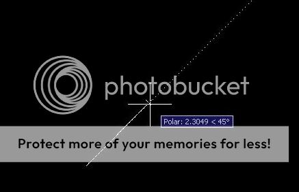 This is called “Polar Tracking”, and that dotted line is called a ‘tracing vector’. It enables you draw quickly along certain angles without given the exact coordinate. You can set which angles autocad will track. Go to Tools > Draft Settings (keystroke: ‘ds’). Select the ‘Polar Tracking’ tab and click on ‘Increment angle’ dropdown menu and choose ‘15’. Then click ok. This means that Polar tracking will now be tracking in increment angles of 15 degrees (i.e. 0, 15, 30, 45, 60, etc.). Oya try to draw a line again; choose anywhere as first point and move the cursor till polar tracking shows up at 30 degrees. Hold it like that (as in, don’t click anything), press ‘5’ on your keyboard and press enter, then enter again to end the line command. See that? You have drawn 5 units line at 45 degrees WITHOUT USING ANY COORDINATE! Chai, u be winsh?? And now, the last two buttons: OSNAP and OTRACK, which are short for ‘Object Snap’ and ‘Object Snap Tracking’. Their shortcuts are F3 and F11 respectively. OSNAP works like the SNAP button, but instead of snapping to grid points, what it does is snap to certain points on the body of any object you already drawn (e.g.: endpoint of a line, center of a circle, midpoint of a line, etc.). To explain better, open ‘Draft Settings’ again and select the ‘Object Snap’ tab; tick on Endpoint, Midpoint, Center, Intersection, Extension, and Perpendicular; and then Ok. Make sure your OSNAP and OTRACK buttons are on. Now, start line command again and bring your cursor crosshairs close to the lower endpoint of that 5 units line you drew earlier; can you see the small box-like OSNAP snapping you to the end of the line? Don’t click yet; bring you cursor slowly downwards in a straight line. Do you see the tracking vector along 270 degrees? If you type ‘5’ and ‘enter’ now, your new line’s first point will be exactly 5 units below the first line. Ok, maybe I’ve confused you a bit. Don’t worry; I’ll explain better with some drawings. The next pic of different shapes below is today’s main work. You can copy and save for reference. We’ll draw them using Object snaps and Object snap tracking. As usual, open a new drawing template (File > New; select ‘acad’ and open). Then draw the border rectangle just like last time (coordinates 0,0 and 20,15). 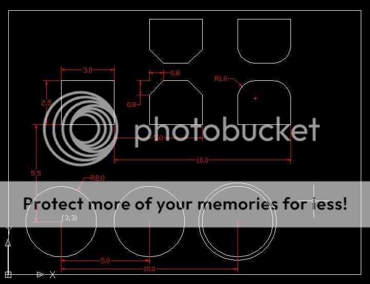 |
| Re: For Interested Engrs: Learn Autocad On This Thread by hal9000: 7:58am On Jul 30, 2013 |
Alrighty. First we start with circle at the lower left corner. Click on the circle icon, or type ‘c’ at command line. _circle Specify center point for circle or [3P/2P/Ttr (tan tan radius)]: Type 3,3 as center point of circle and ‘enter’. Specify radius of circle or [Diameter]: Now move your cursor around to get tracking vector at 45 degrees. Press ‘2’ and ‘enter’. Beautiful! You have drawn a circle with radius of 2 units. Now copy the circle 5 units and 10 units to the right. Type ‘co’ at command line (and click copy icon). Select objects: Click on the circle and ‘enter’ Specify base point or [Displacement] <Displacement>: Move cursor crosshairs around inside the circle till the center Osnap symbol shows (it looks like a small cross inside a small circle). Once it shows, just click your mouse irrespective of where your cursor is. Specify base point or [Displacement] <Displacement> Specify second point or <use first point as displacement>: Now move cursor crosshairs towards your right to get 0 degrees tracking vector, then press ‘5’ and enter. Specify second point or [Exit/Undo] <Exit>: Still on the 0 degrees vector, press ‘10’ and enter. Then ‘enter’ again to end the copy command. If you were able to do that, then congratulations! Let’s move on. Next we will “offset” the third circle 0.2 units. Click on the Offset icon (from Modify toolbar)… Command: _offset Specify offset distance or [Through/Erase/Layer] <Through>: 0.2 ‘enter’ Select object to offset or [Exit/Undo] <Exit>: Click on the third circle (don’t press ‘enter’) Specify point on side to offset or [Exit/Multiple/Undo] <Exit>: Click on space a little distance outside the circle. Select object to offset or [Exit/Undo] <Exit>: Press ‘enter’ to exit the offset command. Voila! You should see your offset circle now. (You can also offset 0.2 units INSIDE the circle as extra practice). Next draw the rectangle 5.5 units above the first circle’s center. The rectangle dimensions are 3 units length and 2.5 units width. You can use tracking vector from the center of circle to mark off the rectangle’s first point. OR you can just draw a line from the circle center 5.5 units in y-direction, and then use the end of the line as first corner point of your rectangle. For second corner point, use relative coordinates to give length and width (hope you remember how it is done? @x,y). Delete the line when you’re done. Now copy that rectangle twice to the right at distances 5 units and 10 units respectively, just as you did with the circle. You can use any corner of the rectangle as base point. Note that you can use the scroll button on your mouse to Zoom in and Zoom out while still in the Copy command; this is very useful in selecting the exact Osnap point that you want to use as your base point. You will now use the ‘Chamfer’ and ‘Fillet’ tools to modify the two copied rectangles (Chamfer and Fillet should be the last two icons on the modify toolbar). A Little Explanation on Chamfer and Fillet: The Chamfer tool is used to create a “chamfer” at the point where two lines meet (often a right angle). The pic below explains better. The chamfer tool has been used there to create a chamfer with chamfer distance of 0.8 units. 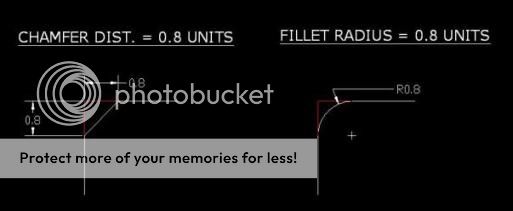 ‘Fillet’ is similar to chamfer, but here you create a curved edge (an arc) instead of a chamfer edge. In that example above, the fillet tool was used to create fillet of radius 0.8units. Alright, let’s go back our original work drawing. We will use chamfer and fillet to modify the two rectangles you copied. We start with the middle rectangle. Select ‘chamfer’ icon (keystroke: ‘cha’) Command: cha CHAMFER Select first line or [Undo/Polyline/Distance/Angle/Trim/mEthod/Multiple]: First we input the chamfer distance, so press ‘d’ to select ‘Distance’ option. ‘Enter’. Specify first chamfer distance <0.0000>: [/i]Type 0.8 for first chamfer distance, enter. [i]Specify second chamfer distance <0.0000>: Type 0.8 for second chamfer distance, enter. Select first line or [Undo/Polyline/Distance/Angle/Trim/mEthod/Multiple]: Time to choose the edges you want to chamfer. Going clockwise, click on the left-side line of the rectangle (shape will change to dotted line), then click on top line of rectangle. Good! Now press ‘enter’ to activate chamfer again, then going clockwise once more click on the rectangle top line, and then the right-side line to complete. Well done! Oya, over to the next rectangle for fillet… Click on the fillet icon or keystroke ‘f’. FILLET Select first object or [Undo/Polyline/Radius/Trim/Multiple]: Press ‘r’ to select ‘Radius’ option, ‘enter’. Specify fillet radius <0.0000>: We’ll use a fillet radius of 1 unit, so press ‘1’ and ‘enter’. Select first object or [Undo/Polyline/Radius/Trim/Multiple]: Just like chamfer we’ll go clockwise. Do the left top corner first, then hit ‘enter’ to activate fillet once again and do the right top corner as well. Sweeeeeeeet! Ok, last thing for today: we’ll use the Mirror tool to make an image of the two modified rectangles 0.5 units above the originals. Click the Mirror icon from modify toolbar (or keystroke: ‘mi’) MIRROR Select objects: Select the two shapes and hit ‘enter’ (tip: to select quickly, you can click a small distance below the right rectangle, then drag left and up to envelop the two shapes. You’ll be sked to “specify opposite corner”; just click when you’ve enveloped the two objects. Hit ‘enter’ when you’re done.) Specify first point of mirror line: Now bring the cursor crosshairs to top of the left modified rectangle, watch for the ‘Midpoint’ Osnap. When it shows, don’t click; just draw your cursor crosshairs upwards to activate the 90 degrees tracking vector. When this shows, just type 0.5 and ‘enter’.  Specify second point of mirror line: Time for some magic! Move your mouse around to see the mirrored shapes following you; position it properly and click. You’ll be asked whether to erase source object; type ‘n’ to select No, and ‘enter’. Bravo!! Oya, for the olodos in the class. Who no get am? See, you can actually just draw a 0.5 units line from the middle of the rectangle and then use it as your first point of mirror line. However to be a good CAD draftsman it’s really necessary that you learn how to use Osnap and Object tracking; that’s why I think you should try until you can use it to mirror objects from a specified distance.ALRIGHT! Time to save your work; save it as Lesson Three, and that’ll be all for today! You can now go and drink your zobo with puff-puff… --- Guys i’m really sorry I couldn’t prepare the extra practice work I promised, it’s been pretty hectic for me. I’ll try and scratch something up so you can practice with it for wednesday. Next class is Friday (sorry for the long break; I think I should be spacing myself now to avoid ‘promise and fail’). Hope to round up Drawing and Modification then. Peace out! |
| Re: For Interested Engrs: Learn Autocad On This Thread by double3(m): 6:34pm On Jul 31, 2013 |
If u guys can take time to follow this instructor,believe me u would know the basics of autocad 2d drafting,its not easy teaching a software as complicated as autocad without physical contact but the op is taking his time to make sure he breaks it down to the basics,good job man. 2 Likes |
| Re: For Interested Engrs: Learn Autocad On This Thread by Reakdchef(m): 11:37am On Aug 01, 2013 |
U are really doing a good job and I appreciate,am a chem engr graduate and based in Porthacourt I will like to hook up wit u to learn more I av auto cad 2013 is ma laptop.des my e-mail add chyke4all@yahoo.com,if u don't mind inbox me ur phone so dat I can give u a call.thanks a lot |
| Re: For Interested Engrs: Learn Autocad On This Thread by prologue: 12:39pm On Aug 01, 2013 |
Nice one bro. Am following. Thanks and God bless |
Soundcraft Academy PRESENTS... (music Production/sound Engineering Training) / Fidelity Bank Aptitude Test Questions / 5 Months Salary Owed. What Should I Do?
(Go Up)
| Sections: politics (1) business autos (1) jobs (1) career education (1) romance computers phones travel sports fashion health religion celebs tv-movies music-radio literature webmasters programming techmarket Links: (1) (2) (3) (4) (5) (6) (7) (8) (9) (10) Nairaland - Copyright © 2005 - 2024 Oluwaseun Osewa. All rights reserved. See How To Advertise. 112 |